Assemble the AeroSpreader Feed Spinner
Use these steps to assemble the feed spinner.

Letter | Part |
|---|---|
A | Upper elbow |
B | Lower elbow |
C | Bearing |
D | Float |
E | Support pole |
F | Counter weight |
G | Bolt protector |
H | Feed pipe coupler |
I | Adjustable nozzle |
The image shows a pole that has 2 pieces. A pole that has 1 piece has only 1 bolt protector at the counterweight.
Tools and Materials You Need
These items are not supplied with the feed spinner.
Wrenches sizes: 12, 13, 15 mm (1/4, 1/2, 9/16 inch)
HDPE feed pipe, outside diameter 88.9 mm (3.5 inches)
Pipe cutter or saw
Knife or deburring tool, to remove rough edges from the feed pipe
A strap wrench for the nut on the compression fitting
Attach the Upper Elbow
Remove the 4 bolts from the bearing.
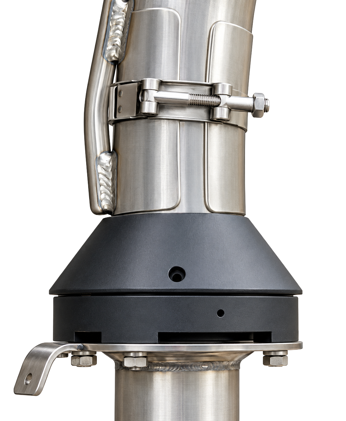
Put the upper elbow on the mount plate. Install the 4 bolts. Do not overtighten the bolts.

The image below shows the completed installation.
Install the Support Pole
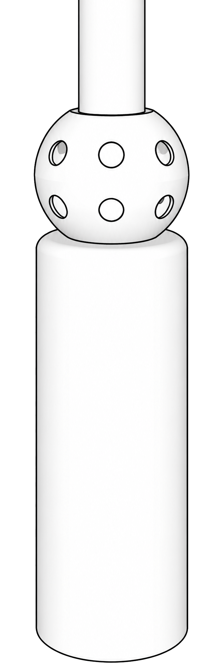
The bolt protectors cover the bolts on the pole. Fish swim near the pole. The end of a bolt can damage the scales of a fish. The bolt protectors prevent this damage.
The support pole is shipped in either 1 piece or in 2 pieces.
Pole that has 1 piece: The 2 ends of the pole are the same. You need 1 bolt protector.
Pole that has 2 pieces: The top piece has a pole connector on the bottom end. You need 2 bolt protectors. For steps 1 to 3, use the top piece.
Slide a bolt protector onto the pole.
Push the top end of the pole through the pipe on the bottom of the float.
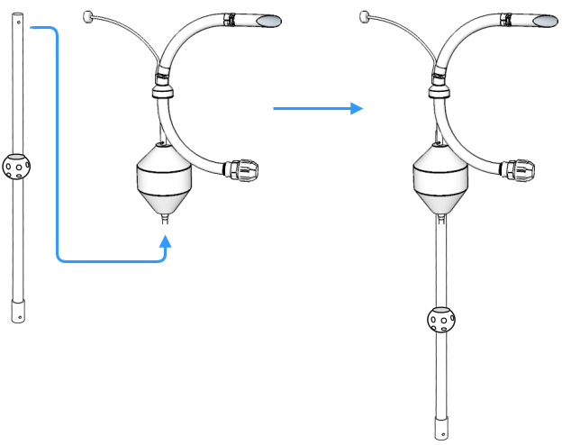
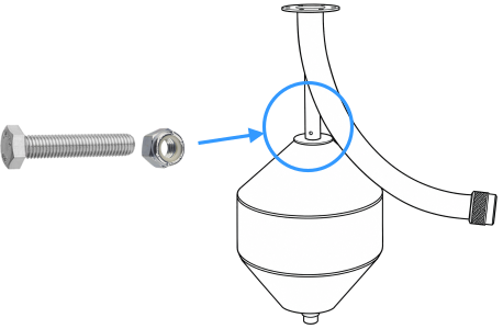
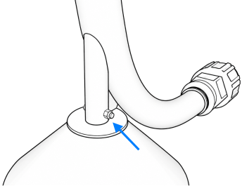
Attach the pole to the lower elbow with the bolt and the lock nut.
Only for a pole that has 2 pieces. If the pole has 1 piece, go to step 5.
Join the bottom piece to the top piece at the pole connector. Use the bolt and nut to secure the 2 pieces together.
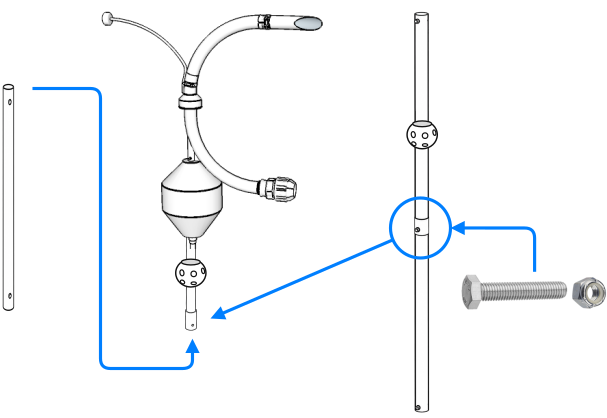
Move the bolt protector down until the bolt protector covers the bolt on the pole.
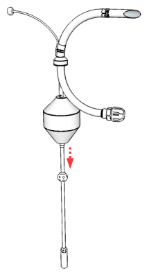
Slide the second bolt protector up onto the bottom end of the pole.
Attach the bottom end of the pole to the counterweight.
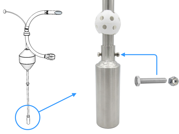
Slide the bolt protector down the pole until until the bolt protector covers the counterweight bolt.
Install the Adjustable Nozzle

Loosen the bolt (A) on the T-bolt clamp at the end of the upper elbow. Then slide the nozzle (B) onto the end of the upper elbow.
Turn the nozzle (B) to set the size of the feed spread.
Turn the nozzle opening down for a smaller spread circle.
Turn the nozzle opening up for a larger spread circle.
Push the nozzle until the edge of the nozzle touches the edge of the upper elbow (C). There must be no gap.
Tighten the bolt (A) on the T-bolt clamp. Do not overtighten the bolt.
Install the Feed Pipe Coupler
The feed pipe coupler fits HDPE pipe with an outside diameter of 88.9 mm (3.5 inches).

Letter | Part |
|---|---|
A | Feed pipe |
B | Nut |
C | O-ring |
D | Coupler body |
Follow these steps to install the feed pipe coupler.
Cut the end of the feed pipe straight, at 90 degrees. Remove any burrs from the cut. Make sure that the end of the feed pipe is clean.
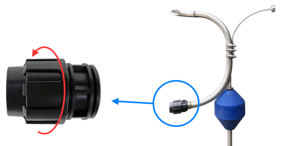
Turn the nut (B) counterclockwise to remove the nut from the coupler body (D).
Slide the parts onto the feed pipe (A) in the order shown. Keep each part in the same order and the same direction as in the image.
Make sure the O-ring (C) is at the end of the feed pipe.
Push the feed pipe fully into the coupler body (D) until it reaches the internal stop.
Slide the parts along the feed pipe toward the coupler body. Turn the nut (B) clockwise by hand. Turn the nut until you cannot turn the nut more by hand.
Tighten the nut using a strap wrench.
Pull on the feed pipe. The feed pipe must not move.